ZPE02: Blinky Application With Zephyr Project
Learn how to fully utilize Zephyr Project GPIO APIs
Getting To Know Board-Level Device Trees
Now that we understand device tree syntax from the previous article, let us start getting our hands dirty by writing a basic application using NRF5340 DK (development kit) board that accepts user inputs from push buttons and blink some of the on-board LEDs based on those inputs. Plus, we will explore a few standard device tree node properties along the way. Starting with the hardware, the following picture provides a quick overview of the board with numerical annotations on some areas of interest for this article.
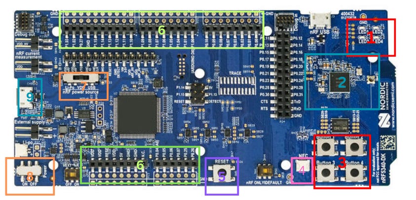
In the above image, the annotated components are:
User LEDs
NRF5340 SoC
User buttons
Antenna connector for NFC
Reset button
Pin Connectors
Slider switch for power sources
Power-on switch
USB connector for on-board J-Link Debugger
A key advantage of using device tree is that application developers don’t need to consult schematics to understand how components like LEDs and buttons are connected to the SoC. A quick look at the vendor-provided board-level DTS (Device Tree Sources) would give us the information we need to utilize the on-board peripheral devices. For example, one of the NRF5340 DK device tree sources describes the on-board LEDs as:
leds {
  compatible = "gpio-leds";
  led0: led_0 {
    gpios = <&gpio0 28 GPIO_ACTIVE_LOW>;
    label = "Green LED 0";
  };
  led1: led_1 {
    gpios = <&gpio0 29 GPIO_ACTIVE_LOW>;
    label = "Green LED 1";
  };
  led2: led_2 {
    gpios = <&gpio0 30 GPIO_ACTIVE_LOW>;
    label = "Green LED 2";
  };
  led3: led_2 {
    gpios = <&gpio0 31 GPIO_ACTIVE_LOW>;
    label = "Green LED 3";
  };
};
Let us explore the standard properties we see here in this example.
Compatible
First, the compatible property is an important property every nodes except the root must have. This property helps the build system determine the node’s bindings and validate it.
Being valid in this context means that the node has a correct syntax, correct required properties, and correct types of values for those properties. In other words, this property basically represents the name of a hardware device, such as gpio-leds in this case.
Then, if the node is valid, the build system generates macros for the properties of the nodes, which can then be called by the device drivers and application codes. Here, the gpio-leds compatible lets you define a group of led nodes where each child node has gpios (required property - a must have, cannot be omitted) and label (optional) properties.
compatibleis a string-array type property and typically follows the“vendor, device”format, for example,compatible=”nordic,nrf-gpio-forwarder”. However, for the nodes likeledsnode in the above DTS, the vendor part is usually omitted if the node characteristics is vendor-independent. Additionally, sometimes the node only include a single element like,gpio-ledsand additional string element may be used as an alias if the build system cannot determine the bindings from the first element.
Node labels
We have not yet introduced node labels in this article. Node labels are often used with device tree APIs such as DT_NODELABEL to get node identifiers. This allows developers to assign custom, human-readable names to pre-existing nodes, which is one of the easy and good approaches to get the node ids. For example, to get the node ID of led_0 in the above DTS, we use DT_NODELABEL(led0) in the application.
Note that node labels and
labelproperties serves different purposes and are not the same.labelproperties are sometimes used for other purposes such as debugging, logging the node’s name and retrieving the node number/index on the parent device/node.
gpios
The gpios property is a phandle-array type with two specifiers where the first specifier represents the GPIO pin number and the second the GPIO flags.
Macros like
GPIO_ACTIVE_LOWcan be defined in a C header file and included from the device tree. For more information on GPIO-related macros, see here.
Now that we are familiar with a few standard properties, from the above leds node we now understand that the DK board has 4 leds connected to pin 28, 29, 30, and 31 of the GPIO0 port. The next section will explore how we can interact with them.
Development Environment Setup
There are 3 ways to setup development environment for a Zephyr Project:
- Use nrfConnect SDK tools if you frequently work with products from Nordic Semiconductor. They provide amazing GUI-based tools for installing all necessary toolchains to get started with the Zephyr project development as quick as possible. Additionally, there is a useful VS Code plugin for nRF Connect that simplifies development with features like device tree views, debugging, and device management.
- Install the toolchains manually. You can refer to this Zephyr Project documentation but it is not recommended because based on your host platform, it may take quite a while to get started if something did not go well in the installation process. You may end up spending more time setting up the environment than doing actual development.
- Use a containerized development environment. We will use Docker for this approach, as it is the quickest way possible. With containers, what works on one machine should work on another regardless of their OS.
You can still follow along with the article even if you are not familiar with Docker. Please refer to this link to learn about Docker.
You can use the Docker image from this repository and follow the instructions in README.md to build the Zephyr Project Docker image and run the containerized build environment.
Your Zephyr workspace should look like this:
zephyr_workspace
├── apps/
├── Dockerfile
├── entrypoint.sh
└── Makefile
We will create a minimal Zephyr application, the “blinky” project inside the apps folder and the project should include:
main.c, for the firmware.prj.conf, for Kconfig.CMakeLists.txt, for the build. Now, the project structure should look like this:
├── apps
│   └── blinky
│       ├── CMakeLists.txt
│       ├── prj.conf
│       └── src
│           └── main.c
├── Dockerfile
├── entrypoint.sh
└── Makefile
Create the CMakeLists.txt with the following contents:
cmake_minimum_required(VERSION 3.20.0)

find_package(Zephyr REQUIRED HINTS $ENV{ZEPHYR_BASE})

project(blinky)

target_sources(app PRIVATE src/main.c)
The prj.conf is typically empty in a starter project but we will populate this file as the development progresses.
But, let us leave it for now.
Right, to verify that the build environment is set up correctly, we can write a simple “Hello World” program that prints “Hello World” to the UART0 peripheral and sends it to the PC via the USB cable. Populate the main.c file with the following contents.
#include <zephyr/devicetree.h>
#include <zephyr/kernel.h>

int main() {
  printf("Hello world");
  return 0;
}
If you have cloned the repository provided earlier, navigate to the workspace directory within the cloned repository and run the following command to build the docker image.
Ensure that the
makeprogram is installed in your host system for the following commands to work.
make build-docker-image
Then, run the following to start the container.
make run-docker-container
This command will start a Debian-based Zephyr Project container and mount the workspace volume into /opt/zephyrproject/zephyr/workshop. Then, you can start using the built-in command line tool called west to build the firmware we just wrote.
Development Workflow
West is a meta-tool provided by Zephyr that allows you to build, flash, debug Zephyr application, sign binaries and do many other interesting tasks. West deserves a separate article for a deeper exploration but here, we will only introduce a few use cases of west that are relevant to this article.
As a first step, we can find out which boards are supported by Zephyr without going to the documentation page by running:
west boards
Results:
root@3d1a07d63aab:/opt/zephyrproject/zephyr/workshop# west boards
weact_stm32f405_core
blackpill_f401ce
mini_stm32h743
blackpill_f411ce
blackpill_f401cc
weact_stm32g431_core
b_u585i_iot02a
stm32g071b_disco
nucleo_l4r5zi
nucleo_u5a5zj_q
steval_fcu001v1
nucleo_f030r8
stm32h750b_dk
..
..
The results show a long list of supported boards. To narrow down the list, we can use filters with the -n option. We will use the option with nrf keyword to check if our NRF5340DK board is included in the list:
west boards -n nrf
Results:
root@3d1a07d63aab:/opt/zephyrproject/zephyr/workshop# west boards -n nrf
nrf52_vbluno52
nrf51_vbluno51
nrf52_sparkfun
nrf52840_papyr
nrf52840_blip
nrf52832_mdk
nrf52840_mdk_usb_dongle
nrf52840_mdk
nrf52_adafruit_feather
adafruit_feather_nrf52840_express
adafruit_feather_nrf52840_sense
nrf9151dk
nrf52840dongle
nrf9131ek
nrf54l15pdk
nrf52833dk
nrf52840dk
nrf5340dk
..
Great! The list shows all the boards with names containing the keyword, “nrf”, including our board, nrf5340dk. You can also use the -f option to print more detailed information about the boards with your preferred format:
west boards -f "{name} => {qualifiers}" -n nrf
Results:
root@3d1a07d63aab:/opt/zephyrproject/zephyr/workshop# west boards -f "{name} => {qualifiers}" -n nrf
nrf52_vbluno52 => nrf52832
nrf51_vbluno51 => nrf51822
nrf52_sparkfun => nrf52832
nrf52840_papyr => nrf52840
nrf52840_blip => nrf52840
nrf52832_mdk => nrf52832
nrf52840_mdk_usb_dongle => nrf52840
nrf52840_mdk => nrf52840
nrf52_adafruit_feather => nrf52832
adafruit_feather_nrf52840_express => nrf52840
adafruit_feather_nrf52840_sense => nrf52840
nrf9151dk => nrf9151,nrf9151/ns
nrf52840dongle => nrf52840
nrf9131ek => nrf9131,nrf9131/ns
nrf54l15pdk => nrf54l15/cpuapp,nrf54l15/cpuflpr,nrf54l15/cpuflpr/xip
nrf52833dk => nrf52820,nrf52833
nrf52840dk => nrf52840,nrf52811
...
Now that you know your board’s name, you can now use west to print out information specifically for your board by specifying its name with the —board option:
west boards -f "{name} => {qualifiers}" --board nrf5340dk
Results:
root@3d1a07d63aab:/opt/zephyrproject/zephyr/workshop# west boards -f "{name} => {qualifiers}" --board nrf5340dk
nrf5340dk => nrf5340/cpuapp,nrf5340/cpuapp/ns,nrf5340/cpunet
The qualifiers is a useful parameter needed during the build process to specify details about your build target. For example, if you’re building a non-secure version of your application firmware, you would use nrf5340/cpuapp/ns. If you’re targeting the network core of the NRF5340 SoC, you would use nrf5340/cpunet.
Now, let us build the firmware with the following west build command and since we do not want to consider the security features yet, we will just use the qualifier for the simple application target, nrf5340/cpuapp:
west build -p always -b nrf5340dk/nrf5340/cpuapp apps/blinky
Results:
root@6d014c305b28:/opt/zephyrproject/zephyr/workshop# west build -p always -b nrf5340dk/nrf5340/cpuapp apps/blinky

-- west build: making build dir /opt/zephyrproject/zephyr/workshop/build pristine
-- west build: generating a build system
Loading Zephyr default modules (Zephyr base).
-- Application: /opt/zephyrproject/zephyr/workshop/apps/blinky
-- CMake version: 3.25.1
-- Found Python3: /opt/zephyrproject/.venv/bin/python3 (found suitable version "3.11.2", minimum required is "3.8") found components: Interpreter
-- Cache files will be written to: /root/.cache/zephyr
-- Zephyr version: 3.7.99 (/opt/zephyrproject/zephyr)
-- Found west (found suitable version "1.2.0", minimum required is "0.14.0")
-- Board: nrf5340dk, qualifiers: nrf5340/cpuapp
-- ZEPHYR_TOOLCHAIN_VARIANT not set, trying to locate Zephyr SDK
-- Found host-tools: zephyr 0.16.5 (/zephyr-sdk-0.16.5)
-- Found toolchain: zephyr 0.16.5 (/zephyr-sdk-0.16.5)
-- Found Dtc: /zephyr-sdk-0.16.5/sysroots/x86_64-pokysdk-linux/usr/bin/dtc (found suitable version "1.6.0", minimum required is "1.4.6")
-- Found BOARD.dts: /opt/zephyrproject/zephyr/boards/nordic/nrf5340dk/nrf5340dk_nrf5340_cpuapp.dts
-- Generated zephyr.dts: /opt/zephyrproject/zephyr/workshop/build/zephyr/zephyr.dts
-- Generated devicetree_generated.h: /opt/zephyrproject/zephyr/workshop/build/zephyr/include/generated/zephyr/devicetree_generated.h
-- Including generated dts.cmake file: /opt/zephyrproject/zephyr/workshop/build/zephyr/dts.cmake
Parsing /opt/zephyrproject/zephyr/Kconfig
Loaded configuration '/opt/zephyrproject/zephyr/boards/nordic/nrf5340dk/nrf5340dk_nrf5340_cpuapp_defconfig'
Merged configuration '/opt/zephyrproject/zephyr/workshop/apps/blinky/prj.conf'
Configuration saved to '/opt/zephyrproject/zephyr/workshop/build/zephyr/.config'
Kconfig header saved to '/opt/zephyrproject/zephyr/workshop/build/zephyr/include/generated/zephyr/autoconf.h'
-- Found GnuLd: /zephyr-sdk-0.16.5/arm-zephyr-eabi/arm-zephyr-eabi/bin/ld.bfd (found version "2.38")
-- The C compiler identification is GNU 12.2.0
-- The CXX compiler identification is GNU 12.2.0
-- The ASM compiler identification is GNU
-- Found assembler: /zephyr-sdk-0.16.5/arm-zephyr-eabi/bin/arm-zephyr-eabi-gcc
-- Using ccache: /usr/bin/ccache
-- Configuring done
-- Generating done
-- Build files have been written to: /opt/zephyrproject/zephyr/workshop/build
-- west build: building application
[1/135] Preparing syscall dependency handling

[2/135] Generating include/generated/zephyr/version.h
-- Zephyr version: 3.7.99 (/opt/zephyrproject/zephyr), build: v3.7.0-1625-gf29377a12cb5
[135/135] Linking C executable zephyr/zephyr.elf
Memory region         Used Size  Region Size  %age Used
           FLASH:       19884 B         1 MB      1.90%
             RAM:        4416 B       448 KB      0.96%
        IDT_LIST:          0 GB        32 KB      0.00%
Generating files from /opt/zephyrproject/zephyr/workshop/build/zephyr/zephyr.elf for board: nrf5340dk
The -p option stands for pristine, with three choices available: always, never, and auto. In the example above, always means that each time the command is run, the existing build directory will be cleaned, and the application will be rebuilt from scratch. The auto choice allows the build system to decide whether everything or just part of the application needs to be rebuilt.
While the always pristine build ensures a clean build, it can be significantly slower than auto for large codebases. So, choose this option wisely to control the build process.
Now connect your board to the PC and flash the firmware with:
west flash
Results:
root@811c26a4fc90:/opt/zephyrproject/zephyr/workshop# west flash

-- west flash: rebuilding
[0/16] Performing build step for 'tfm'
ninja: no work to do.
[2/13] Performing install step for 'tfm'
-- Install configuration: "MinSizeRel"
----- Installing platform NS -----
[13/13] Linking C executable zephyr/zephyr.elf
Memory region         Used Size  Region Size  %age Used
           FLASH:       20784 B       192 KB     10.57%
             RAM:        4544 B       192 KB      2.31%
        IDT_LIST:          0 GB        32 KB      0.00%
Generating files from /opt/zephyrproject/zephyr/workshop/build/zephyr/zephyr.elf for board: nrf5340dk
image.py: sign the payload
image.py: sign the payload
-- west flash: using runner nrfjprog
-- runners.nrfjprog: reset after flashing requested
You can use serial monitor software like minicom to see the console output from the DK board UART. Specify the port with the -D option, in this case /dev/ttyACM1. This can be different on your host platform:
minicom -D /dev/ttyACM1
Results:
Welcome to minicom 2.8

OPTIONS: I18n
Port /dev/ttyACM1, 11:12:14

Press CTRL-A Z for help on special keys

*** Booting Zephyr OS build v3.7.0-1625-gf29377a12cb5 ***
Hello world
If you do not see the log, try pushing the reset button as it might have already been printed out and the console did not catch it.
A Brief Introduction To Device Tree APIs
We will use the following APIs to interact with GPIO devices:
gpio_is_ready_dt- to validate if the GPIO port connected to the LEDs is ready.gpio_pin_configure_dt- to configure the LED pins as GPIO output that are turned off at initialization stage.gpio_pin_interrupt_configure_dt- to configure the push buttons as interrupt driven GPIO inputs.gpio_pin_set_dt- to turn on and off the LEDS.
We should also be familiar with the following data structures:
struct device- a structure representing an instance of peripheral device. (gpio, i2c, spi, etc.)struct gpio_dt_spec- a structure containing data fields such as port, pin, and dt_flag.
The above structs must be created but should not be populated manually. Their values will be filled out by the Device Tree APIs such as DEVICE_DT_GET for struct device and GPIO_DT_SPEC_GET for struct gpio_dt_spec.
Now, we are ready to write our first blinky application.
Let us enable GPIO APIs by setting CONFIG_GPIO=y in the prj.conf file:
CONFIG_GPIO=y
And include the following header files at the top of the main.c file:
#include <zephyr/devicetree.h>
#include <zephyr/drivers/gpio.h>
#include <zephyr/kernel.h>
<zephyr/devicetree.h>for device tree APIs<zephyr/drivers/gpio.h>for GPIO driver APIs<zephyr/kernel.h>for kernel services likek_msleepfor delaying some intervals between on/off states of the LEDs.
We will obtain device tree specifications for each on-board LED using GPIO_DT_SPEC_GET. This macro populates an instance of struct gpio_dt_spec with properties defined in the device tree sources with the gpio-leds compatible. It takes two arguments: node_id and property.
You can obtain the node_id of a device tree node using several APIs such as DT_ALIAS, DT_CHOSEN, DT_NODELABEL, etc. We will use DT_NODELABEL as it is more convenient to use the node labels (led0, led1, led2, and led3) in this example as they are already defined by the board-level source tree. If you are interested in other API, see this link.
Here is one way to create instances representing the 4 LED pins in the global scope:
const struct gpio_dt_spec led0 = GPIO_DT_SPEC_GET(DT_NODELABEL(led0), gpios);
const struct gpio_dt_spec led1 = GPIO_DT_SPEC_GET(DT_NODELABEL(led1), gpios);
const struct gpio_dt_spec led2 = GPIO_DT_SPEC_GET(DT_NODELABEL(led2), gpios);
const struct gpio_dt_spec led3 = GPIO_DT_SPEC_GET(DT_NODELABEL(led3), gpios);
The GPIO_DT_SPEC_GET macro uses the node id returned by DT_NODELABEL and use the gpios property to get the specifications of a GPIO pin. Although, the above code works, it contains some duplication and can be improved as follows:
enum { LED0, LED1, LED2, LED3 };

const struct gpio_dt_spec led_dt_specs[4] = {
    [LED0] = GPIO_DT_SPEC_GET(DT_NODELABEL(led0), gpios),
    [LED1] = GPIO_DT_SPEC_GET(DT_NODELABEL(led1), gpios),
    [LED2] = GPIO_DT_SPEC_GET(DT_NODELABEL(led2), gpios),
    [LED3] = GPIO_DT_SPEC_GET(DT_NODELABEL(led3), gpios)};
The improve code packs all the device tree specs into a single array, which reduces code duplication and allows the repeated operations to be performed in a loop. Let us initialize the LEDs as GPIO pins as follows:
int main() {
  for (size_t i = {0}; i < ARRAY_SIZE(led_dt_specs); i++) {
    if (!gpio_is_ready_dt(&led_dt_specs[i])) {
      printf("%s: pin %d is not ready.\n", led_dt_specs[i].port->name,
             led_dt_specs[i].pin);
      return -EBUSY;
    }
    printf("%s: pin %d is ready.\n", led_dt_specs[i].port->name,
           led_dt_specs[i].pin);
    int ret = gpio_pin_configure_dt(&led_dt_specs[i], GPIO_OUTPUT_INACTIVE);
    if (ret < 0) {
      printf("Failed to initialize %s: pin %d. Error code: %d",
             led_dt_specs[i].port->name, led_dt_specs[i].pin, ret);
      return ret;
    }
    printf("%s: pin %d is successfully initialized.\n",
           led_dt_specs[i].port->name, led_dt_specs[i].pin);
  }
  return 0;
}
First, we iterate through the led_dt_specs to do the same initialization steps for all the LED pins. ARRAY_SIZE macro returns the number of elements in the given array.
Before any initialization, the GPIO devices are checked if they are ready first with the gpio_is_ready_dt and then configured as a GPIO output pin with intial LOW state by calling the gpio_pin_configure_dt function with the GPIO_OUTPUT_INACTIVE flag.
Zephyr uses POSIX compliant error codes where functions return non-zero integer values to indicate an issue in a operation. So, we check this error code in the above example and let the code break out of the main function if any device initialization did not succeed.
Now we will make the LEDs blink one after another with 500 milliseconds intervals between on/off states within an infinite loop. k_msleep is an RTOS service that makes the current task (caller) enter sleep mode for a given time period in terms of milliseconds. gpio_pin_set_dt can be used to set the state of the given GPIO spec. It also returns an error code, which is omitted here for the sake of simplicity.
while (1) {
  static int led_state = 1;
  for (size_t i = {0}; i < ARRAY_SIZE(led_dt_specs); i++) {
    gpio_pin_set_dt(&led_dt_specs[i], led_state);
    k_msleep(500);
    gpio_pin_set_dt(&led_dt_specs[i], !led_state);
    k_msleep(500);
  }
}
Here is the complete code for the blinky application.
#include <zephyr/devicetree.h>
#include <zephyr/drivers/gpio.h>
#include <zephyr/kernel.h>

enum { LED0, LED1, LED2, LED3 };

const struct gpio_dt_spec led_dt_specs[4] = {
    [LED0] = GPIO_DT_SPEC_GET(DT_NODELABEL(led0), gpios),
    [LED1] = GPIO_DT_SPEC_GET(DT_NODELABEL(led1), gpios),
    [LED2] = GPIO_DT_SPEC_GET(DT_NODELABEL(led2), gpios),
    [LED3] = GPIO_DT_SPEC_GET(DT_NODELABEL(led3), gpios)};

int main() {
  for (size_t i = {0}; i < ARRAY_SIZE(led_dt_specs); i++) {
    if (!gpio_is_ready_dt(&led_dt_specs[i])) {
      printf("%s: pin %d is not ready.\n", led_dt_specs[i].port->name,
             led_dt_specs[i].pin);
      return -EBUSY;
    }
    printf("%s: pin %d is ready.\n", led_dt_specs[i].port->name,
           led_dt_specs[i].pin);
    int ret = gpio_pin_configure_dt(&led_dt_specs[i], GPIO_OUTPUT);
    if (ret < 0) {
      printf("Failed to initialize %s: pin %d. Error code: %d",
             led_dt_specs[i].port->name, led_dt_specs[i].pin, ret);
      return ret;
    }
    printf("%s: pin %d is successfully initialized.\n",
           led_dt_specs[i].port->name, led_dt_specs[i].pin);
  }
  while (1) {
    static int led_state = 1;
    for (size_t i = {0}; i < ARRAY_SIZE(led_dt_specs); i++) {
      gpio_pin_set_dt(&led_dt_specs[i], led_state);
      k_msleep(500);
      gpio_pin_set_dt(&led_dt_specs[i], !led_state);
      k_msleep(500);
    }
  }
  return 0;
}
Now if we build and flash the program as described earlier, you will see the console log output as follows:
Welcome to minicom 2.8

OPTIONS: I18n
Port /dev/ttyACM1, 14:19:21

Press CTRL-A Z for help on special keys

*** Booting Zephyr OS build v3.7.0-1625-gf29377a12cb5 ***
gpio@842500: pin 28 is ready.
gpio@842500: pin 28 is successfully initialized.
gpio@842500: pin 29 is ready.
gpio@842500: pin 29 is successfully initialized.
gpio@842500: pin 30 is ready.
gpio@842500: pin 30 is successfully initialized.
gpio@842500: pin 31 is ready.
gpio@842500: pin 31 is successfully initialized.
Also, you can see the blinking LEDs as shown in the following video. Now let us add button inputs for our Zephyr application. In the nrf5340dk_common.dtsi,the buttons are defined as:
buttons {
    compatible = "gpio-keys";
    button0: button_0 {
            gpios = <&gpio0 23 (GPIO_PULL_UP | GPIO_ACTIVE_LOW)>;
            label = "Push button 1";
            zephyr,code = <INPUT_KEY_0>;
    };
    button1: button_1 {
            gpios = <&gpio0 24 (GPIO_PULL_UP | GPIO_ACTIVE_LOW)>;
            label = "Push button 2";
            zephyr,code = <INPUT_KEY_1>;
    };
    button2: button_2 {
            gpios = <&gpio0 8 (GPIO_PULL_UP | GPIO_ACTIVE_LOW)>;
            label = "Push button 3";
            zephyr,code = <INPUT_KEY_2>;
    };
    button3: button_3 {
            gpios = <&gpio0 9 (GPIO_PULL_UP | GPIO_ACTIVE_LOW)>;
            label = "Push button 4";
            zephyr,code = <INPUT_KEY_3>;
    };
};
Blink LED Demo
Cool! Now, we will create another struct gpio_dt_spec array for the buttons:
const struct gpio_dt_spec led_dt_specs[4] = {
    [BUTTON0] = GPIO_DT_SPEC_GET(DT_NODELABEL(button0), gpios),
    [BUTTON1] = GPIO_DT_SPEC_GET(DT_NODELABEL(button1), gpios),
    [BUTTON2] = GPIO_DT_SPEC_GET(DT_NODELABEL(button2), gpios),
    [BUTTON3] = GPIO_DT_SPEC_GET(DT_NODELABEL(button3), gpios)};
From the device tree, we can say that buttons are pulled up by default. So, we should configures these pins as interrupt driven pins which triggers on the pin state change to zero with gpio_pin_interrupt_configure_dt and the GPIO_INT_EDGE_TO_INACTIVE flag.
// Initializes the Buttons
for (size_t i = {0}; i < ARRAY_SIZE(button_dt_specs); i++) {
   if (!gpio_is_ready_dt(&button_dt_specs[i])) {
      printk("%s: pin %d is not ready.\n",
             button_dt_specs[i].port->name,
             button_dt_specs[i].pin);
      return -EBUSY;
    }
    int ret = gpio_pin_configure_dt(&button_dt_specs[i],
                                   GPIO_INPUT);
    if (ret < 0) {
      printk("Failed to initialize %s: pin %d as GPIO input.
      Error code: %d",
             button_dt_specs[i].port->name,
             button_dt_specs[i].pin, ret);
      return ret;
    }

    ret = gpio_pin_interrupt_configure_dt(
                    &button_dt_specs[i],
                    GPIO_INT_EDGE_TO_INACTIVE);
    if (ret < 0) {
      printf("Failed to initialize %s: pin %d. Error code: %d",
             button_dt_specs[i].port->name,
             button_dt_specs[i].pin,
             ret);
      return ret;
    }
    printk("%s: pin %d is successfully initialized.\n",
           button_dt_specs[i].port->name, button_dt_specs[i].pin);
}
We create callback functions/interrupt service routines for each button GPIO pin.
static uint8_t button_pin_pushed = {0};

void on_button0_pressed(const struct device *dev, struct gpio_callback *cb, uint32_t pins) {
  printk("Button 0 pressed.\n");
  button_pin_pushed = BUTTON0;
}

void on_button1_pressed(const struct device *dev, struct gpio_callback *cb, uint32_t pins) {
  printk("Button 1 pressed.\n");
  button_pin_pushed = BUTTON1;
}

void on_button2_pressed(const struct device *dev, struct gpio_callback *cb, uint32_t pins) {
  printk("Button 2 pressed.\n");
  button_pin_pushed = BUTTON2;
}

void on_button3_pressed(const struct device *dev, struct gpio_callback *cb, uint32_t pins) {
  printk("Button 3 pressed.\n");
  button_pin_pushed = BUTTON3;
}
Every time one of the callbacks is executed, we assign the global variable, button_pin_pushed, with the enum value representing the “Push” event so that the LEDs can be turned on with different patterns based on these button events. The following two functions are required for this purpose.
gpio_init_callbackgpio_add_callback
We can call these two functions in the button initialization loop like this:
// Initializes the Buttons
for (size_t i = {0}; i < ARRAY_SIZE(button_dt_specs); i++) {
/**
* Do other stuffs
**/
gpio_init_callback(&button_cb_data[i], button_handlers[i],
                       BIT(button_dt_specs[i].pin));
gpio_add_callback(button_dt_specs[i].port, &button_cb_data[i]);
/**
* Do other stuffs
**/
}
button_handlers and button_cb_data holds an array of button callback and callback data, respectively. These two are declared as global variables at the top of the file as:
static const gpio_callback_handler_t button_handlers[4] = {
    on_button0_pressed, on_button1_pressed, on_button2_pressed,
    on_button3_pressed};

static struct gpio_callback button_cb_data[4] = {0};
We can now flash the program into the board to see how the LEDs behave. The following video provides a sense of what the output should look like. The complete code is in the provided repository’s blinky folder.
Buttons Demo
Thank you for reading!
Stay tuned for more of contents like this! I will continue to post Zephyr Project related contents and talk about other firmware related topics in the upcoming articles.
Useful Resources
- NRF5340 DK device tree - nrf5340dk_common.dtsi - https://github.com/zephyrproject-rtos/zephyr/blob/main/boards/nordic/nrf5340dk/nrf5340dk_common.dtsi
- West - https://docs.zephyrproject.org/latest/develop/west/index.html