ZPE01: How to quickly get started with Zephyr Project - Device trees
Porting firmware to different processor architecture has never been easier!
Writing portable firmware that works out of the box on different processor architectures is a challenging task. Your team has spent an extravagant amount of time building a code base completely dependent on a series of system-on-chips (SoCs) supplied by a single vendor for years.
At one point, a feature request from a customer arises that requires your team to use a particular SoC from a different vendor, which is based on a completely different processor. For example, the firmware your team has built has become so large that it is tightly coupled to vendor-specific toolchains.
Additionally, it has become quite a task to port the entire code base to a different SoC architecture without spending years—or months if your team is exceptionally skilled—just to modify the existing code base to fit a new SoC. Most of the time, companies cannot afford this, and it would not make your manager happy either.
Zephyr Project
The Zephyr Project by the Linux Foundation is a firmware development framework that provides a straightforward way to port firmware from one SoC architecture to another, with just a few configuration changes, making developers’ lives easier.
In this article series, we will develop a simple blinking LED application, which serves as the “hello world” of embedded software engineering, and test it on a development board from Nordic Semiconductor called the nRF5340 DK.
We will then examine how convenient it is to port the code to a different platform, such as the ESP32 dev board. To follow along with the experiment, you will need the following hardware:
- NRF5340 DK (You can also use other DKs like the nRF52 DK from Nordic Semiconductor) - https://www.nordicsemi.com/Products/Development-hardware/nRF5340-DK
- ESP32 dev kit (from Espressif Systems) - https://www.espressif.com/en/products/devkits
- 4 x 1k resistors
- 4 x LEDs
Why NRF5340 DK and ESP32?
The reason for choosing the nRF5340 DK and ESP32 for this lesson is to highlight the complete difference in their processor cores. The former is based on Cortex-M33 processors, while the latter is based on the Xtensa LX6 processor. Additionally, these two development boards can readily be purchased from distributors like Digikey, Mouser, and similar sources, or even local suppliers if you are lucky.
Another reason for selecting these boards is that they are supported by the Zephyr Project, which means that Zephyr already has device drivers, board support packages (BSPs), RTOS services, and other utilities for these boards. Therefore, you need to verify that your boards are included in the list of supported boards before using the Zephyr Project. However, it is more likely that Zephyr already supports them unless you are using a very old, deprecated board or, conversely, a brand-new board that was just released by a vendor.
Configuring Zephyr
Zephyr provides device drivers, sensor libraries, OS services, various scheduling algorithms, security features, and more. You will often need to manage two configuration frameworks—device tree and Kconfig—to interact with these Zephyr components throughout the development lifecycle.
Kconfig
Kconfig is used to enable or disable components (such as drivers, middleware, or specific code sections), define default values, or set preprocessor macros. In the past, configurations were managed manually using C header files, which became increasingly cumbersome as the project grew. Kconfig, which has been around for a while, is widely used to simplify this process. The build system uses Kconfig files to generate the C-style header file autoconf.h, which can then be included by the application firmware. Kconfig options are written in files with a .conf extension.
Device tree
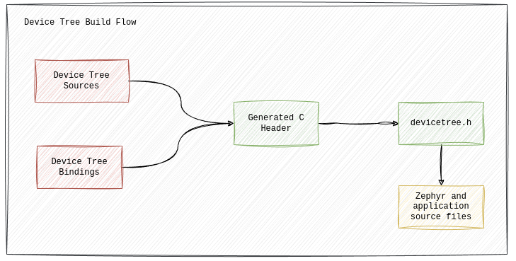
Device trees can be thought of as a hardware description language that tells the build system which implementations of device drivers or other low-level services should be included in the build process based on their descriptions. Here is how the Zephyr documentation describes a simplified version of the device tree build flow:
When we refer to “hardware description language”, it is for the sake of simplicity in explaining the concepts and should not be confused with the real hardware description language like VHDL or verilog for FPGAs. Also note that Zephyr uses the device tree at build time, unlike the embedded Linux environment, where the device tree is loaded at boot time.
Device tree build flow
The Zephyr build system looks at both device tree sources and device tree bindings to generate a C header file, devicetree_generated.h, that contains APIs usually starting with the prefix DT_. Application code and other Zephyr components may call these APIs to interact with the resources. Device tree bindings are YAML files that specify how a particular node should be defined, including its properties and the types of those properties. During the build, the syntax of the device tree sources is checked first, followed by their requirements based on the bindings (which we will explore later). When valid nodes are found, C macros corresponding to the properties in those nodes are generated.
Device tree file formats
Device tree files use one of these extensions: .dtsi, .dts, or .overlay. In this context, dts stands for ‘device tree source,’ while dtsi stands for ‘device tree source include,’ as the contents of .dtsi files are usually included by other higher-level device tree files. Therefore, .dtsi files commonly contain SoC-level definitions, whereas .dts files contain board-level definitions. Both types of files use the same syntax, and the choice of extension is based on conventions.
In terms of properties, the file extensions do not differ. However, another type of device tree source file, called overlays, is often used to override the default properties in the built-in .dts files.
For application development, it is a good practice to use overlays than to modify the built-in sources provided by Zephyr.
Before we dive into Devicetree APIs in those generated headers, let us look at some of the built-in Zephyr device tree sources files to get familiar with the syntax and learn how we can write, extend or modify these sources in our own applications.
Device tree Syntax
Every tree-like structure has a root and child (or leaf) nodes, and the device tree is no different. In a device tree, every node has an ID and properties that define its characteristics. The root node is represented as /, while child nodes can be named according to the context. Here is the basic syntax for a device tree source file.
// Root Node
  / {
  // Child Node
  node_a {
      // Node properties here
         };
  // Child Node
  node_b {
      // Node properties here
         };
    };
The device tree above shows a root (/) with two child nodes: node_a and node_b. Properties for each node go inside curly braces and end with a semicolon (;).
Since there are a lot of properties in the Zephyr bindings index, we will focus on just a few standard ones and those relevant to the example nodes in this article. However, if you’re curious about all the details, you can check out the device tree specifications or the Zephyr bindings index for more info on Zephyr-specific properties.
Device tree Properties
Each property of a tree node is a name and value pair, which is normally written with the following syntax.
Property values come in different types with their own syntax. We will look at a few common ones that you will often see in board-level and SoC-level Zephyr device trees, like int,boolean, string, phandle, and array. If you run into a type that is not covered here, you can always check the device tree specification for more details.
Property value types
Integer type properties usually represent single values, like clock-frequency or easydma-maxcnt-bits, where you just need to set one value for these hardware parameters. You can describe an integer property like this, where 10000 is the 32-bit integer value:
my-int32-prop=<10000>;
Whether the value is in Hz or MHz depends on how the property is defined in the device tree bindings. Also, if you need to use a 64-bit integer, it should be written as two 32-bit values in big-endian order:
my-u64-prop=<0x12345678 0x9ABCDEF0>;
In device tree specs, a “cell” is defined as a 32-bit unit of information.
Boolean type properties are often used to indicate whether a feature exists in a node. These properties are sometimes called ’empty properties’ because the property name is written without any value on the right side to show a true status. If the property is missing, it means false.
String type properties are obviously a double quoted text written as:
my-string-prop=”hello”;
Phandle type properties are like pointers in C. Instead of pointing to a memory address, a node can be referenced with a phandle by using (&) followed by the node name:
my_node {
// Write properties here
};

&my_node {
// Using phandle to overwrite properties of my_node
};

other_node {
// Using phanle as a property value
phandle-to-my_node=&my_node;
};
The syntax above also shows that you can overwrite or extend a node’s characteristics using a phandle. This approach is sometimes used with device tree overlays, which we will cover later in this series.
Array type properties are collections of values. There are different types of arrays: array (32-bit), uint8-array, string-array, phandles, and phandle-array. Here’s how you can describe them:
Q: Why are some values written in hex format and some in decimal in my-array?
A: In Zephyr, integer values are usually assumed to be 32-bit by default. You can write a 32-bit integer in either hex or decimal format—whichever you prefer. The example above is just for demonstration. But be careful with integers of other sizes. For example, an 8-bit integer in my-uint8-array should be written in hex format without the 0x prefix, and a 64-bit value should use the 2-cell format as described earlier.
Q: Why are there two types of arrays that contain phandles?
A: It can be a bit confusing at first. A phandle is like a reference or pointer to a node, so a phandles is essentially a list of these “references”. On the other hand, a phandle-array includes compound elements where each element consists of a phandle and additional cells called specifiers. The details of what each specifier means or how many there are in a particular phandle are defined in the bindings.
Thanks for reading!
We will cover hands-on experiments on writing a blinky application using Zephyr Project on the upcoming episodes. Stay tuned!